This section gives a brief description of the Talos missile and booster. For much more information and references see the Talos MIssile History section.
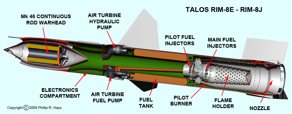
The Talos missile launch configuration consisted of a wing guided ramjet propulsion missile and a solid propellant booster rocket. The missile airframe was a long hollow tube that formed the ramjet engine. At the forward end the warhead innerbody was bolted to the airframe on four struts. The innerbody was an aerodynamic shape that functioned as the compressing element for the ramjet engine. A cowling fit around the warhead to form the compression chamber. A pitot tube and homing antennas were attached to the front of the cowling. Four moveable wings controlled the direction of the missile, and four fixed fins at the rear provided stability.
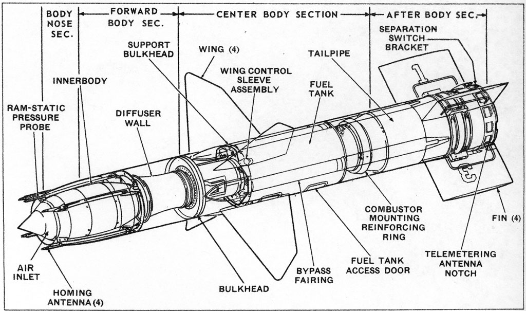
Aft of the warhead a cylindrical electronics compartment wrapped around the central tube. Behind this was a mechanical section containing air turbines, electrical generators and hydraulic pumps. These were located between the wing sockets. Hydraulic actuators located in this section provided wing motion for steering. Aft of the mechanical compartment the fuel tank wrapped around the ramjet tube. In the RIM-8A the tank carried about 70 gallons of JP-5 fuel, giving the missile a range of about 60 nautical miles (69 miles). RIM-8C and later versions had an 85 gallon fuel tank giving a range of 100 nautical miles (115 miles) with JP-5 and 130 nautical miles (150 miles) with JP-4 fuel.
Behind the fuel tank the internal tube of the engine expanded to the tailpipe with the nozzle at the rear end. Around the engine tube were compartments where telemetry equipment could be installed for test shots. Inside the ramjet tube was the ramjet engine, or "burner." The hot high pressure gasses from the burner escaped through the exhaust nozzle at the rear of the missile.
At the tail end of the missile were sockets for the four non-moveable fins and a flange for mounting the missile to the booster. Between the fin positions were several openings that allowed air to flow through the ramjet while it was still attached to the booster during the boost phase. These were necessary to prevent the air column from resonating like an organ pipe before the booster separated. The guidance and telemetry antennas were located at the aft end of the missile.
Electronics and control package
Power for the control hydraulics was generated by an air turbine that was driven by air compressed by the motion of the missile through the atmosphere. Some of the high pressure air from the ramjet intake flowed through the turbines and then vented to the outside.
Most of the electronics were located in modules fitted into compartments just forward of the wings, wrapping around the central ram jet tube. Early versions had vacuum tube circuits, using tubes designed for operation under high G forces. The tube circuits were bulky and the number of functions that could be crammed into the electronics space was limited. These were replaced with transistorized circuitry in the 1960s, followed by integrated circuits in the 1970s. Each new generation of electronics reduced the volume and weight of the circuitry necessary to control the missile, and made room for new and improved features. In the late 1960s a new anti-radiation electronics package was developed to allow the missile to actively home on enemy radars.
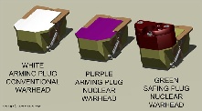
A socket in the side of the missile carried an Arming Plug that completed the connections in the missile control and warhead firing circuits. The missile would not function without the appropriate Arming Plug. This plug was removed and a test umbilical was installed in the socket during missile testing. Missiles carrying a conventional high explosive warhead used a white Arming Plug. Nuclear equipped missiles used a purple Arming Plug. The two plugs were not electrically interchangeable. While in the Area 2 ready service or Area 3 storage magazines conventional warhead missiles carried an ordinary white Arming Plug and nuclear armed missiles had a green Safing Plug installed in the socket.
Contact and proximity fuses
The missile contained two fusing systems to detonate the conventional high explosive warhead. On the tip of the warhead nose cone was a contact fuse that detonated the warhead if the missile made physical contact with the target. This was mostly a formality, because the 3400 pound missile colliding with the target at a relative closing rate of Mach 2.7 possessed enough kinetic energy to destroy nearly any target. Add to this the flammable magnesium alloy airframe and jet fuel, and the result was a huge explosion. During a test exercise off the California coast the USS Oklahoma City fired a surface-to-surface shot without a warhead and caused such extensive damage that the target ship (a decommissioned DE) eventually broke into two parts! Many of the Okie Boat's surface-to-air test shots against Firebee drones resulted in skin-to-skin contact.
The missile carried four proximity fuse radar antennas along the sides of the fuselage just aft of the cowl on the surface of the electronics compartment. These antennas transmitted a conical waveform forward of the missile along the line of flight. If the target passed into this cone and reflected the signal back to the antennas the warhead was detonated.
Continuous rod warhead
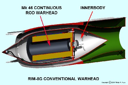
The Mk 46 conventional warhead for Talos contained a 225 pound high explosive core in the shape of a hollow cylinder. The explosives were surrounded by a multi layer shell of long thin steel rods. At one end a rod was joined with the neighboring rod above or below, and at the other end it was connected to the rod to one side. The result was a shell of rods connected together in a "zig-zag" or "daisychain" fashion.
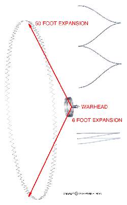
When the explosive detonated the expanding gasses pushed the shell of rods outward, with each rod-to-rod connection bending to maintain a continuous ring of metal
out to a diameter of about 120 feet. Beyond this distance the ring broke and one or more "strings" of rods continued to move outward.
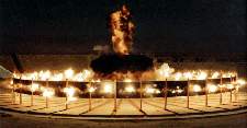
A common static test of this warhead was to support it vertically at the center of a circular area surrounded by a chain-link fence or a wall of aluminum plates.
When the warhead was detonated the expanding rod sliced through the entire circumference of the fence about half way between the top and bottom.
By repeating this test with different diameter fence circles it was possible to determine the effective range of the expanding rod.
When detonated in flight, because of the combination of forward motion of the missile and outward motion caused by the explosion, the expanding ring cut through a conical path in the air. This conical trajectory was identical to the cone projected by the proximity fuse antennas. Consequently, the expanding rod had 100% probability of hitting any target that triggered the proximity fuse at a range of less than 60 feet. Because of the lightweight construction of aircraft the expanding rod would slice the target into two or more parts.
W30 warhead
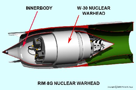
Talos could also carry a W30 nuclear warhead with a yield of about 0.5 kiloton. The purpose of this warhead was to allow engagement of large numbers of enemy bombers at a distance with a single missile. The flash of the explosion would blind pilots looking in the direction of the explosion, the electromagnetic pulse would damage aircraft electronics, and the blast would destroy aircraft up to a half mile of the detonation. The yield was low so a high altitude air burst would not damage ships on the surface below. The nuclear warhead could also be used against surface targets, either ships or shore facilities.
The fissile material for this weapon was Oralloy, uranium (U235). Much of the energy of the warhead came from a tritium boost of the uranium fission explosion. Tritium has a relatively short half-life of 12.3 years (half of the tritium will decay in about twelve years). Consequently, warheads had to be returned to nuclear weapons service facilities regularly to have the tritium reservoirs refilled. A warhead with a freshly filled reservoir could have a yield greater than 0.5 kiloton, while an older reservoir might give a lower yield.
Ramjet sustainer
The missile airframe was basically a long hollow tube with a warhead ogive at the front. Air flowing into the cowling around the warhead was compressed and heated. Jet fuel was injected into the air stream and ignited aft of the flame holder baffle. The expanding gasses of the burning air-fuel mixture propelled the missile forward. Ramjets are very efficient engines. This allowed Talos to achieve a long operating range with a relatively small fuel load.
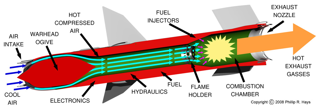
To function a ramjet must be moving fast enough to achieve adequate compression of the air entering the intake. The booster accelerated the missile to the necessary speed, but as soon as the booster burned out the missile started slowing down because of air drag. It was necessary to separate the missile from the booster and ignite the ramjet before the missile slowed below critical ramjet operating speed. The missile and booster were held together by a clamp ring that fitted over flanges on the mating surfaces of the missile and booster. An explosive squib opened the clamp ring allowing the missile and booster to separate. At this moment the booster obstructed the opening in the ramjet nozzle. If the engine was ignited the pressure would blow apart the missile. Ignition must be delayed until the booster fell away far enough to give an area between the booster and the ramjet exhaust at least equal to the exhaust nozzle opening area.
While the booster was accelerating the missile to operating speed the ramjet was taking in air and compressing it inside the ramjet tube. The compressed air flowed through the missile and escaped at the rear through the boost phase air vents around the engine nozzle. The area of these openings was calculated to let enough air escape to attain a pressure of about 45 psia in the combustion chamber at booster separation. This compressed air pushed against the missile and booster, forcing them apart when the mating ring opened.
Missile-booster separation required careful timing, with a 60 millisecond delay between booster separation and ramjet ignition. A 100 millisecond delay was considered the maximum (although missiles with up to a 1 second delay have flown). Ignition had to happen within a 40 millisecond window. The missile had a spark gap igniter (with a pyrotechnic squib as a backup). The spark igniter operated throughout the flight to ensure reignition in case of a flameout. Atmospheric conditions, missile temperature and the dynamics within the ramjet tube created condensation on the igniter during launch that could cause ignition failure. To achieve reliable ignition the igniter was pulsed with a high energy spark to boil away any moisture and break through resistance that may have formed over time on the igniters.
Fuel was introduced into the airstream ahead of a pilot burner and the main burner. The pilot fuel-air mixture was ignited, and the burning mixture flowed into the combustion chamber around the truncated cone flame holder. The main fuel-air mixture passed through the flame holder where it was ignited by the pilot burner flame. A nozzle at the rear of the missile produced the necessary pressures to sustain combustion. Additional air flowed through a narrow channel between the missile frame and a jacket around the combustion chamber to carry heat away from the airframe.
The missile accelerated to Mach 2.7 within 10 seconds after launching. An interesting characteristic of a ramjet is the faster it goes, the faster it goes. The higher the speed the more air is ingested and compressed. This allows more fuel to be burned, producing greater thrust, and making the missile go even faster. If allowed to continue the missile would accelerate to very high speeds where air friction would overheat the airframe and the missile would burn up. The guidance system regulated fuel flow to control airspeed to about Mach 2.7, keeping heating from air friction just below the melting point of the airframe. However, during long flights some of the cowling leading edge was thought to melt away.
Solid propellant booster
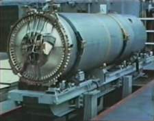
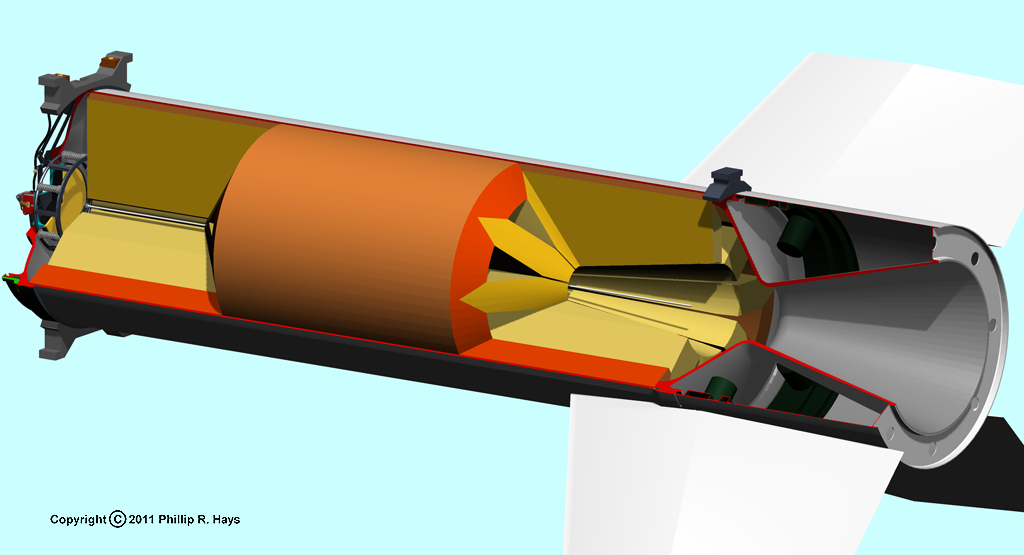
Talos used a Mk 11 Mod 2 solid fuel booster rocket to launch the missile from the ship and carry it to altitude and speed for the missile's ramjet sustainer engine to operate. The booster generated enough thrust to propel the missile to Mach 1 in about two seconds. The booster burned for about 5 seconds, accelerating the missile to Mach 2.2. After the booster fuel was expended a clamp ring around the base of the missile opened to allow the missile and booster to separate.
The forward end of the booster carried the clamp ring that attached the missile and booster. At the rear of the booster were four sockets for non-moveable fins. The booster had two launching "shoes" on the top that fit into the rails of the launch system, a forward two piece shoe just behind the clamp ring and a rear "T" shaped shoe between the fins. An identical set of handling shoes on the bottom of the booster were used to latch the booster into the storage trays in the ready service magazine.
The 2800 pounds of Class B explosive solid fuel in the booster had a star-shaped grain composed of two types of propellants with numerous cavities to produce a high burning rate. A Mk 177 igniter fit into the case forward of the fuel cavity. The four ignition squibs were normally rotated to a safe position where they could not ignite the igniter charge. On the launcher a rod extended to rotate the squibs into position to fire the booster. After ignition the internal chamber pressure rose to 1000 psia for about 5 seconds until the fuel was spent, generating a thrust of 109,800 lbf, or about 50,000 horsepower at Mach 2.2. The clamp ring that held the missile and booster together had a pneumatic device operated by booster internal pressure to open the ring to separate the missile and booster after the fuel burned out.
The ship carried 46 boosters, for a total of 129,000 pounds of class B explosives (nitrocellulose, or gun cotton, dissolved in nitroglycerine). This explosive slowly decayed, releasing extremely flammable diethyl ether into the atmosphere in the magazines. It was necessary to maintain continuous circulation of fresh air through the magazines to avoid accumulation of explosive concentrations of ether.
